
Have you ever had an idea you wanted to turn into reality but didn't know where to start? I know the feeling. I kept seeing things around the house I could fix or improve if only I knew how to design for a 3D printer. Even more came to mind if I knew how to add some hardware and circuits to the mix. This build is an introductory one. The build is designed to help familiarize you with the possibilities. Join me as we dive into 3D modeling, printing, circuits, and programming by building a smart lamp.
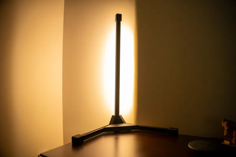
While planning the series, I wanted a poetically nerdy project to keep me motivated. Sitting amidst a pile of parts from an old 3D printer, I wondered, "What if I could turn these parts into a lamp?" Not just any lamp, but one shaped like the X, Y, Z coordinate system we design in. Then the printer could shine on!
This article steps through the assembly.
This project is meant to be fun and hands-on, but it does involve tools, soldering, and working with electricity. Take your time, wear eye protection, and use the right gear for the job. Double-check your wiring before plugging anything in, and if you're ever unsure, ask someone experienced for help. A little caution goes a long way toward keeping your project safe and enjoyable.
Choosing Your Materials
A few specifications matter more than the exact products you buy.
Aluminum extrusion
"2020" means the profile measures 20 mm by 20 mm. You need two 10-inch legs and one 19-inch post, give or take a couple of inches. The grooves let you bolt parts anywhere along the length, which is why you'll find this material in 3D printers, shelves, test rigs, and enclosures. You can cut it with a miter saw, hand saw, or rotary tool; a fine-tooth blade works best and keeps the cut clean.
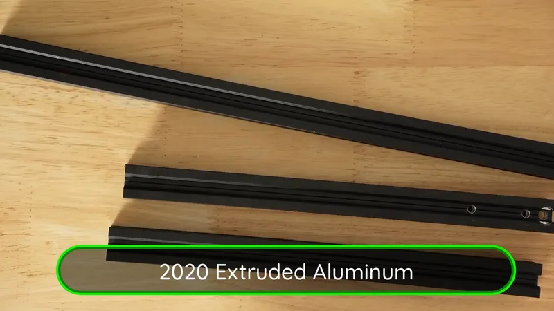
One property matters today: aluminum conducts electricity. The black anodized coating helps, but it scratches easily and the freshly cut ends are bare metal. Keep uninsulated wires away from it.
If you pick up more than you need, no worries. I bet you'll find a use for the leftover. Maybe you'll even make a pair of these lamps for bedside tables.
Power supply
You need a 5 V supply rated for at least 2 A. Don't substitute a 9 V or 12 V supply; the LEDs and microcontroller are designed for 5 V.
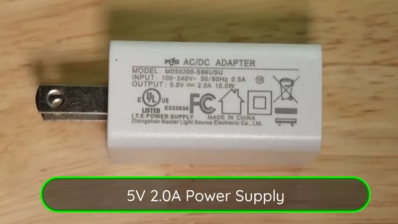
Think of volts as the pressure in your water pipes. Too much and the faucets blast off the wall; too little and nothing comes out. Amps are the size of the pipe. The line into your house is large, but each faucet only draws what it needs. Our LEDs work the same way: they only pull as much current as they need, so a supply rated higher than 2 A is fine. A supply rated below 2 A, though, can cause flickering, odd colors, or an overheated adapter.
Many older USB phone chargers output 5 V at 2 A, so you may already have one in a drawer.
Filament
The rigid parts (base and brackets) print in PLA. The end caps print in TPU so they flex over the extrusion and grip it.
Widget KC Smart Lamp Kit (or similar)
This project needs a handful of small parts, so I put together a kit that gathers them in one place. The kit includes:
- ESP8266 microcontroller and header pins
- Circuit board, screw terminal blocks, and a 1000 µF capacitor
- RGBW LED strip (30 LEDs)
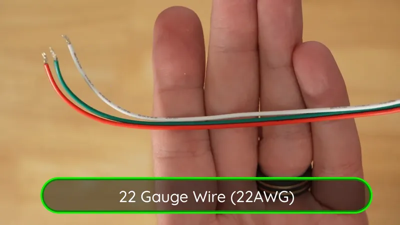
- Three 12-inch lengths of 22-gauge wire
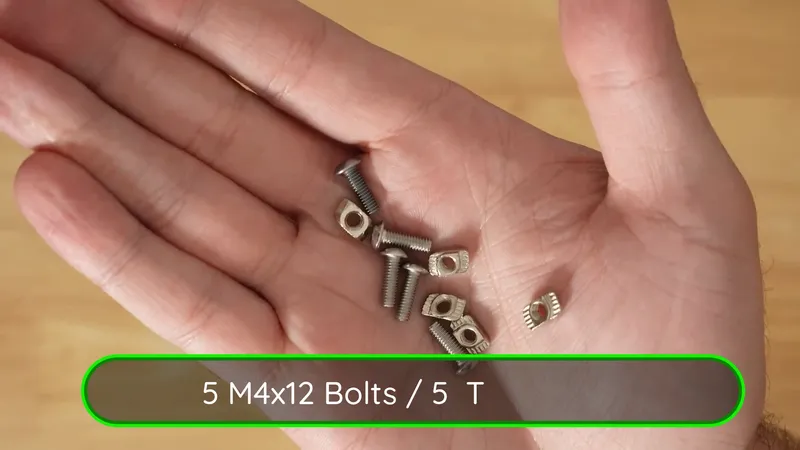
- Five M4x12 bolts and five T-slot nuts
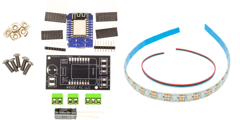
If you'd rather source all the parts yourself, the links are included on this page.
Nuts and Bolts
Wire and LEDs
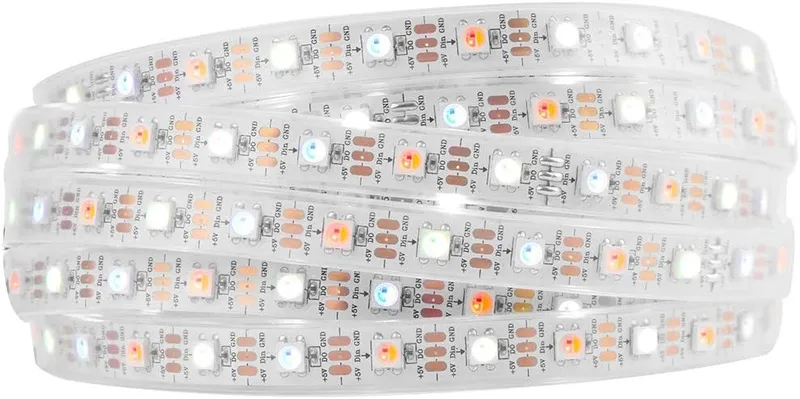
The LED strip is RGBW at 60 LEDs per meter; the lamp uses about 30 of them. Each white square on the strip holds a red, green, blue, and dedicated white emitter, and you can mix them to produce millions of colors. I chose warm white because it best replicates an incandescent bulb.
Look for a strip with an IP65 rating. IP65 is a dust and water rating, but the silicone sleeve that earns it also insulates the strip's contacts from the aluminum, which is what we actually care about here.
Circuit Components
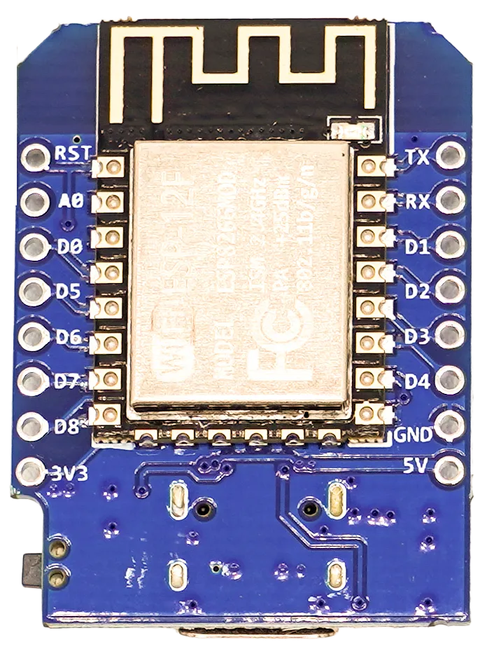
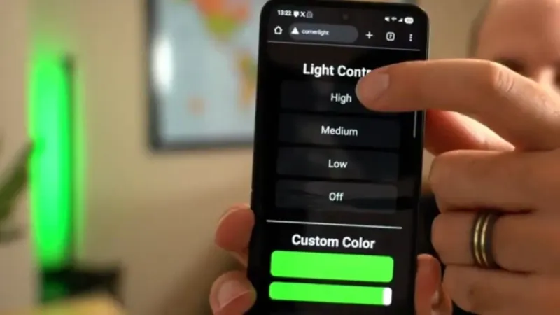
The lamp's brain is the ESP8266 microcontroller. It connects to WiFi and serves the web page you use to control the lamp.
Let's Start Building
Prepare the Aluminum
Cut two 10-inch pieces and one 19-inch piece. An end cap hides one end of each piece, so only one end of each needs a clean cut.
Cut and Solder the LED Strip
The project requires some soldering. If you're new to it, check out our beginner through-hole soldering quickstart first.
Cut the strip to about 30 LEDs. Cut straight across the copper solder pads between any two LEDs; the LEDs will only continue to work if the cut is made at those pads.
Use red wire for positive, green for signal, and white for negative. If you use different colors, keep careful track of which is which.
Look for the small triangles printed on the strip. They point in the direction data flows. Solder your wires to the pads at the flat side of a triangle (the tail of the arrow). If you solder to the pointed end, the lamp won't light.
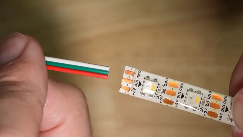
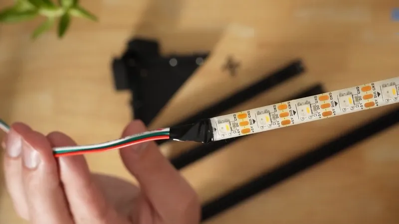
Wrap each connection in electrical tape. We'll fish these wires through the aluminum post, and although the anodized coating helps, the cut edges are bare metal and can short an exposed joint.
Assemble the Base
Insert the 5 bolts into the base and thread a T-slot nut onto each. Attach the two 10-inch legs by sliding them into the base and then tightening down the bolts.
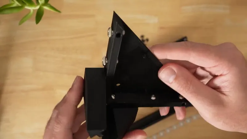
We'll attach the post next. Press the grommet into the opening where the post's wires will pass. It keeps the wires off the sharp cut edge of the extrusion.
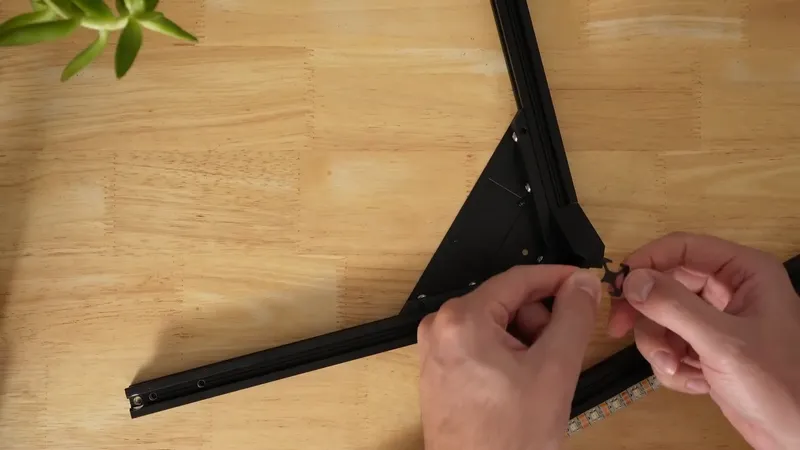
Slide the LED strip into one channel of the 19-inch post and center it between the ends.
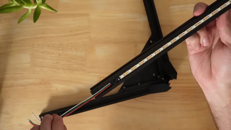
Feed the strip's wires through the grommet and along the channel in the base, then seat the post onto the base and tighten its bolt.
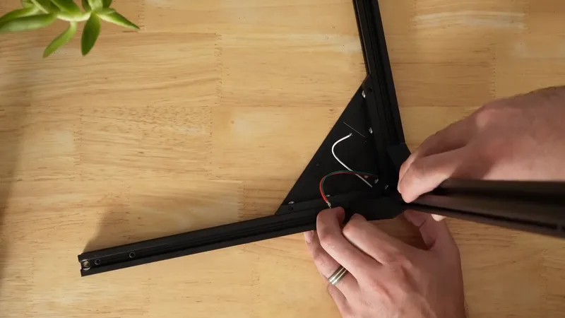
Press a TPU end cap onto the open end of each leg and the post. They cover the cut edges and keep the lamp from sliding. There is also a TPU pad to place at the bottom of the post under the lamp.
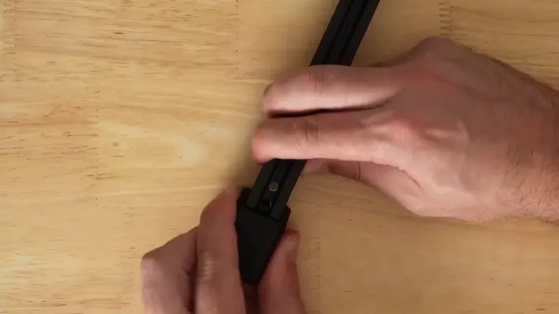
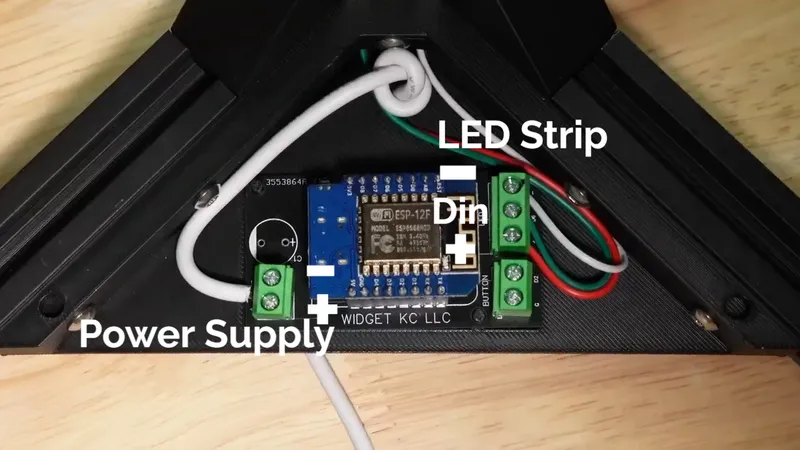
Feed the power cord through the hole in the base and tie a knot inside so a tug on the cord can't pull wires off the board. Connect the LED and power wires to the screw terminals on the circuit board, then give each one a gentle tug to make sure it's secure.
Getting Smart
The ESP8266 gets programmed before it goes into the lamp. With it removed from the lamp's circuit board, plug it into your computer with a USB cable. Download the Widget KC Upload Utility, select 3D Printed Smart Lamp, and follow the prompts to upload the program.
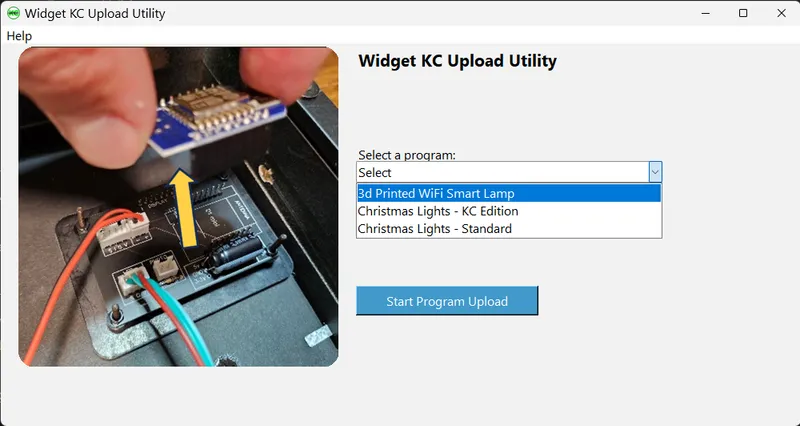
After the upload finishes, the ESP8266 broadcasts its own WiFi network named led_lamp followed by numbers. Connect to that network. If the setup page doesn't appear automatically, open a browser and type http://192.168.4.1 for the address.
On the lamp interface, choose your home network, enter its password, and set a device name without spaces. The name becomes the lamp's hostname, so write it down. After you save, the ESP8266 reboots and joins your network. From a browser on the same network, open http://<device-name>. If that doesn't work, try http://<device-name>.local, or look up the lamp's address in your router's device list and enter http://192.168.1.200 but using the IP address of your specific device.
Once the control page appears, unplug the ESP8266, seat it in the lamp's circuit board in the correct orientation, and power on the lamp.
Congratulations! This project not only lights up your room but also sharpens your printing, circuit, and programming skills. Thanks for joining me, and may your future be bright!
Next Steps
The follow-up project adds a physical brightness button so you can control the lamp without WiFi: Upgrade Your Smart Lamp to Work Without WiFi.
Disclaimer
This project involves the use of tools, soldering equipment, electricity, and other materials that can pose risks if not handled properly. By following the instructions provided here, you agree to take full responsibility for your own safety and the outcome of your project. The information is provided "as is" without any warranties, express or implied. I make no guarantees regarding the performance, safety, or suitability of this project. Always use proper safety precautions and consult a qualified professional if you are unsure. I assume no liability for any injury, loss, or damage resulting from the use or misuse of this information.